PARTS AND MAINTENANCE OF TIPPLER
The place where the wagon is placed , to be tippled , is called table . On to the table the rail is fixed with clamps , it is a detached portion from the ground rail. There is a safe gap of 10 to 12 mm maintained between the table and ground rail , so that when the platform rises for tippling it doesn't collides with the rail on the ground.
How do one know's the position of wagon on table ?
For positioning of wagon there lies a curved convex portion on rail , on the table , for the wheels of wagon to exactly sit without movement during tippling process. When the wagon is tippled at an angle of 80° , there lies a structure called ARMS , with rubber pads attached to them.
The Arms hold the wagon from free fall in to the hopper . The tippler tipples the wagon till an angle of 135° ,in this position the wagon is completly rested on the arms. They are just free moment equipment , they are not rotated by any external means , the arms are connected to a rigid structure with a pin in a journal . As we see the construction of a wagon , the wagon body is mounted on a spring on an axle with wheels attached . so when the wagon is lifted the axle is automatically rotated , so when tippling , at an angle of 135° there is a chance of the axle to get rotated and it doesn't position itself on the table , when the process is completed. To avoid that , a plate of 16mm X 2000mm is welded to support the wheels of the wagon , at exactly the position where the wagon placement takes place.
How tippling takes place ?
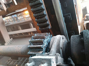
So a machine to run , it needed some form of energy , here an Electric motor of power 130 Kw drives the unit with 440 volts. It is coupled to a reducer of ratio 1:30 . The coupling is a drum coupling , where a thruster brake with 8000 Nm spring force for braking the torque is used . The reducer output is coupled with gear coupling to an intermediate shaft with two pinions on each side of the tippler . The tippler consists of a rack assembly bolted to its body with M30 bolts.
The tippler stucture is supported by rollers which are mounted on to the foundation
So when the motor rotates the electrical energy is converted to mechanical energy with the power transmission line aka coupling,reducer , shaft. So when the shaft rotates the pinion rotates as it is shrink fitted on the shaft , which in turn rotates the tippler as it is meshing with the rack.
Operational Safety
From the wagon placement to tippling and again after completion of tippling , the placement of table position to ground level , is an operating cycle. If in case of emergency an operator choses to stop the tippling process at any angle from ground , he operates the stop push button , so the comand via PLC goes to thruster brake and the brake is applied , which avoids the free fall or movement of tippler. All electrical sensors and mechanical limits are placed for safe and smooth operation. Electrical interlocks and software limits are provided and monitored constatantly to avoid failures.
Maintenance of system
After the operation is completed, that is after a rake is handled, Luberication is done at pivotal points . Pivotal points are the upper structure of of tippler rotating ,plummer blocks ,intermidiate shaft with gear couplings.EP3 at points where wear and tear is more i.e where journal is present and thick film is required.EP2 at plummer blocks where bearings are present.
Compound is applied to rack and pinion for every possible intervals. The intermidiate shaft gear coupling bolts needed to be checked after every rake completion. when the wagon is being tippled it rests on the wall of tippler, where rubber pads were used, need to check regularly and change if damaged, otherwise the main structure would get indentation and damage . Weekly the rollers underneath the table needed to be checked, if damaged needed to be changed. All the bolt and nut assemblies along the tippler need to check for tightness. All the bearings had to be checked physically, any sign of damage , need to escalate and changed. For positioning of ballast tank (It is the counterweight for the wagon when tippling ) there are pendulum's on both sides with a locking wedge , which needed to be inspected for any damages and wear out.


Comments
Post a Comment